This article will explain the steps needed to cut a design with the CNC Plasma Cutter. This tutorial is used in classes in BARN’s Metal Fabrication Studio.
THE INSTRUCTIONS BELOW ARE A DRAFT AND SHOULD NOT BE USED FOR PRODUCTION WORK!
The CNC Plasma Cutter should never be used unless there is a monitor present who is sanctioned to use the machine.
Pro tip: Plasma CNC can be navigated via three different control mechanisms: mouse click, touchscreen, and keyboard commands. Using the keyboard hot keys indicated in this document (see square brackets [ ]) is typically the most efficient. The touchscreen, while intuitive, is not as precise and sometimes an unintended touch target can be activated.
Pro tip: When using Plasma CNC, you can always press “Escape” to revert to the application’s home screen.
1) Take off the Blue Cover and fold up.
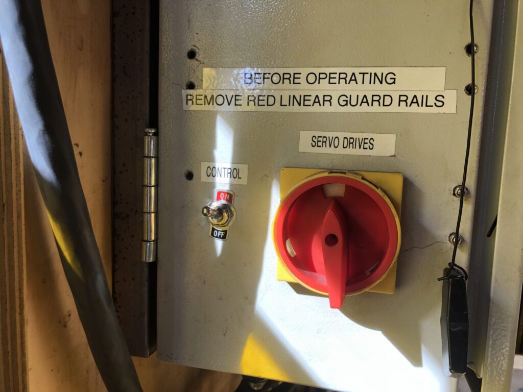
2) Take off the Red X Rail Guards and stand next to the doors on either side of the table.
3) Remove the White Table Top Sheets.
4) Work with a monitor to check the water level on the table – the gap between the water line and the top of the slats should 3 inches.
Filling instructions for monitors:
Open the blue handle valve, the small black valve, and plug in the reserve tank pump in the outlet to the left. Pump water until the water level reaches the desired level.
If the submersible pump is not and/or water is not circulating around table, pull the pump up to clean the inlet of debris if needed. Reposition to ensure flow.
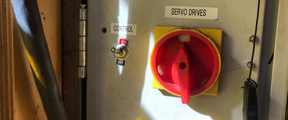
5) On the left side of main panel located on the wall, turn on control toggle switch and turn the servo drive rotary dial clockwise 90 degrees so it is pointing upward.
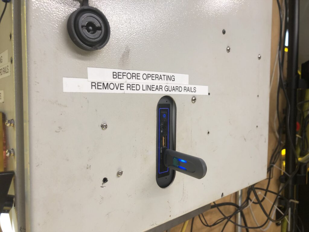
Insert the USB drive into the front of the main panel.
6) The computer will boot up. Open these instructions. After the computer boots up, double-click on the Plasma CNC icon to start the CNC program.
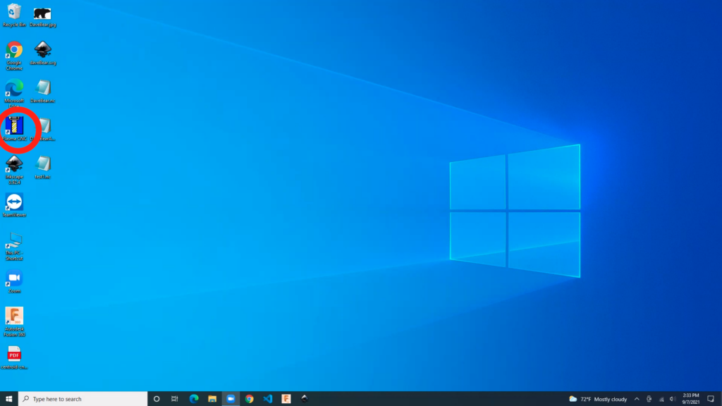
6) The computer will boot up. Open these instructions. After the computer boots up double click on the Plasma CNC icon to start the CNC program.
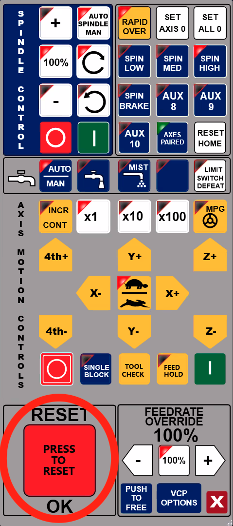
7) After the program has finalized start-up, push the large Red Reset button to clear.
“4032 Reset cleared” will show on the command pane.
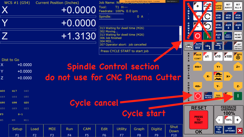
8) Press the Cycle Start button once to start the process.
Should an error dialog render stating “HomeAll switch tripped!!,” press the Cycle Cancel [escape] button to go back.
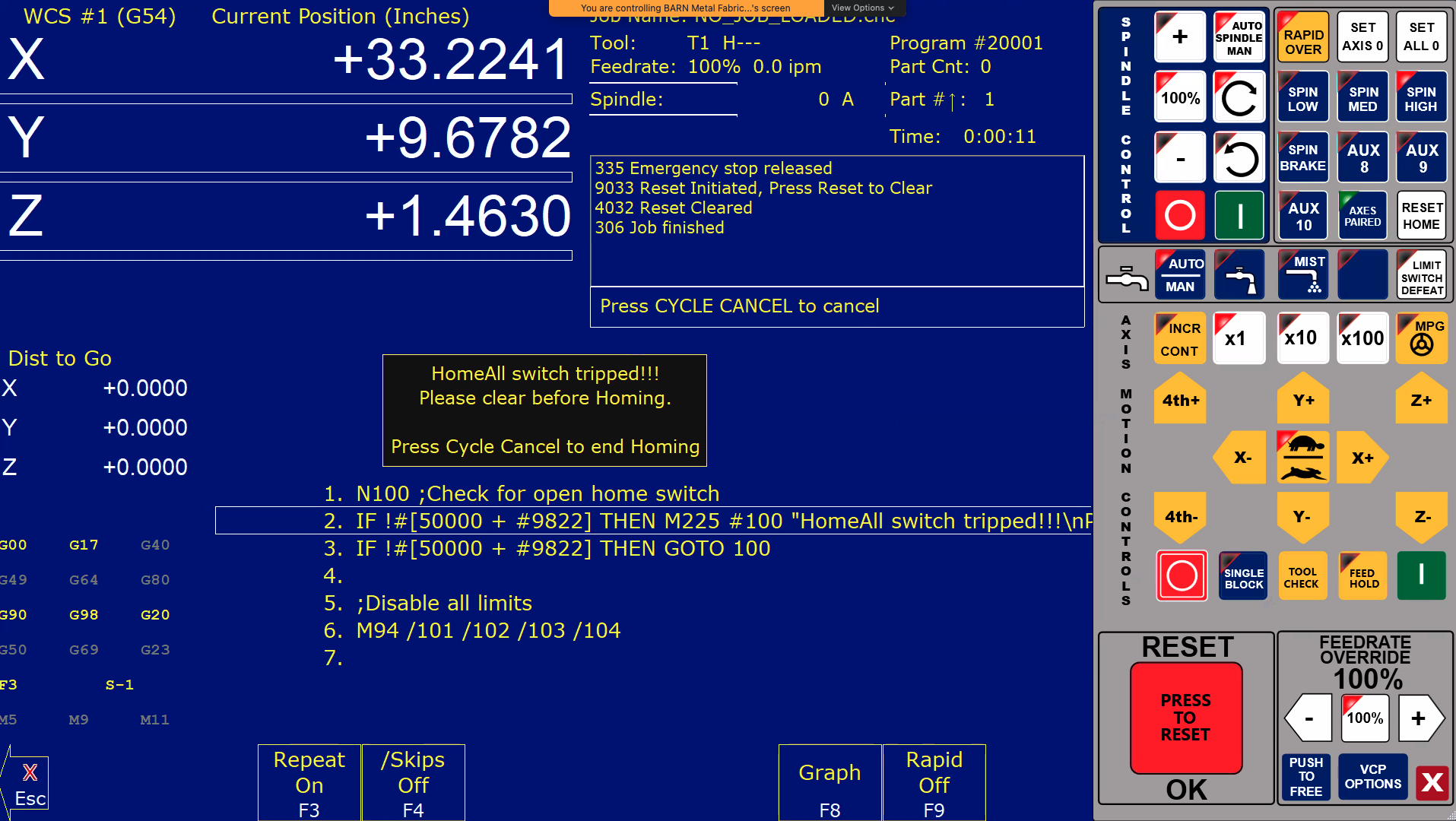
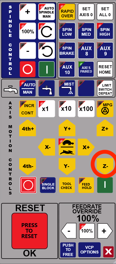
Move the z axis down a small amount using the “Z-” button.
Press Cycle Start.
If the error message is still present, repeat the steps directly above to move the Z down a small amount and press Cycle Start again.
Once all errors have been cleared, press Cycle Start a final time.
9) Now X, Y, and Z numbers should render on the display.
Ensure the table is clear of obstacles.
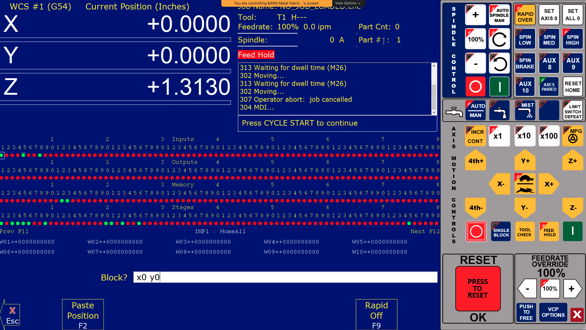
Press the MDI button on the bottom of the display [F3]. Type “x0 y0” in the input labeled Block.
Press Cycle Start.
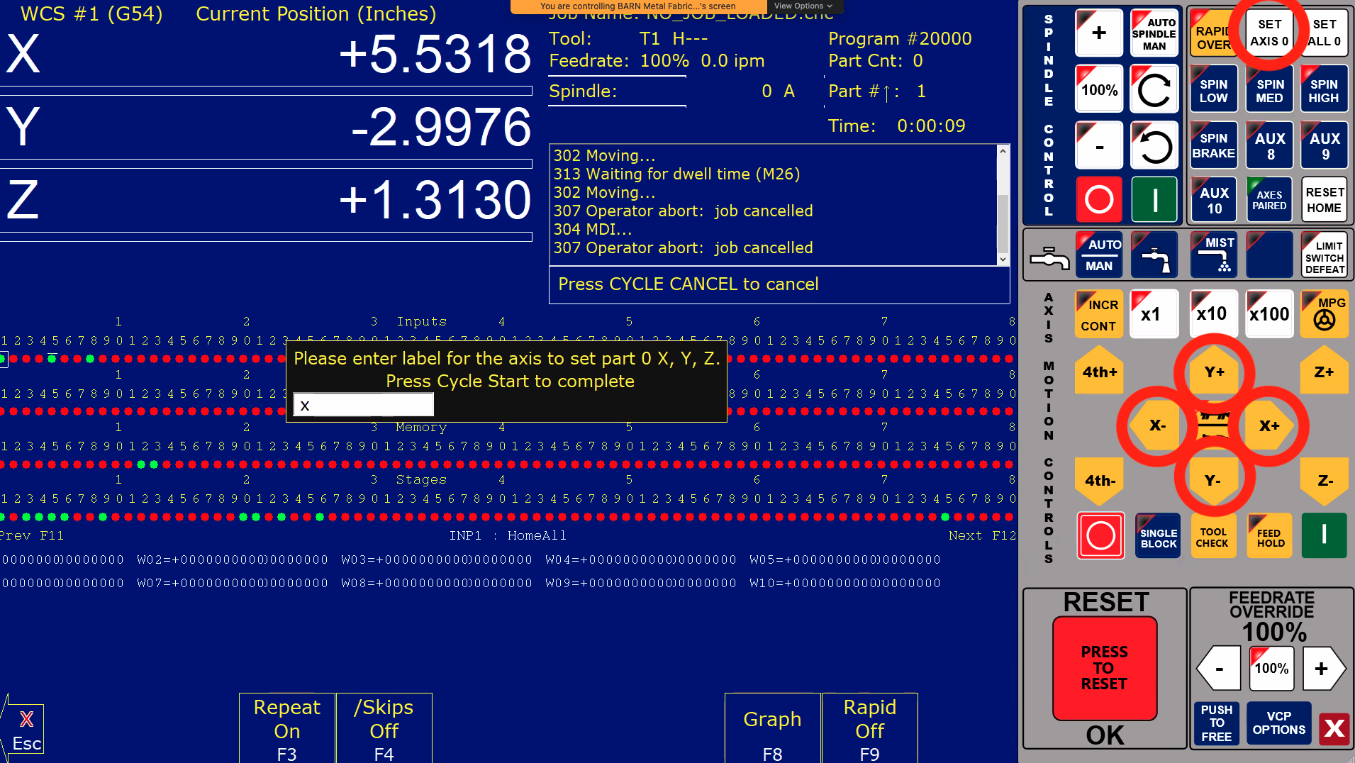
10) Set the new origin for the gantry depending on the size/positioning of the material using one of the following methods:
- Use the knobs on the handheld pendant to change the X and Y and press the “=0+” button to set the new 0 axis.
- Change the X and Y using the Axis Motion Controls touch icons on the display. Press “Set Axis 0” in the top right. Enter either X or Y to zero that axis. Press Cycle Start to accept the new coordinate definition.
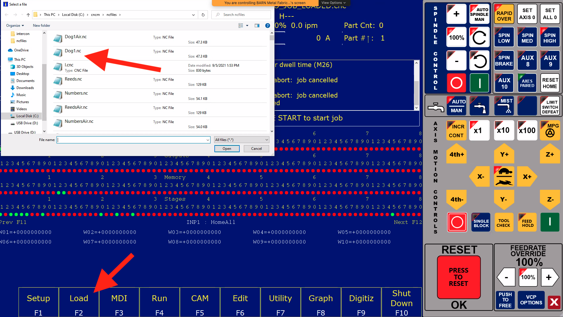
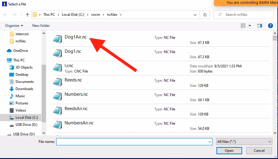
11) Select the Load button on the bottom of the display [F2] and select the desired file using the file browser dialog. Click Open.
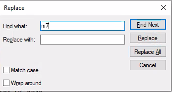
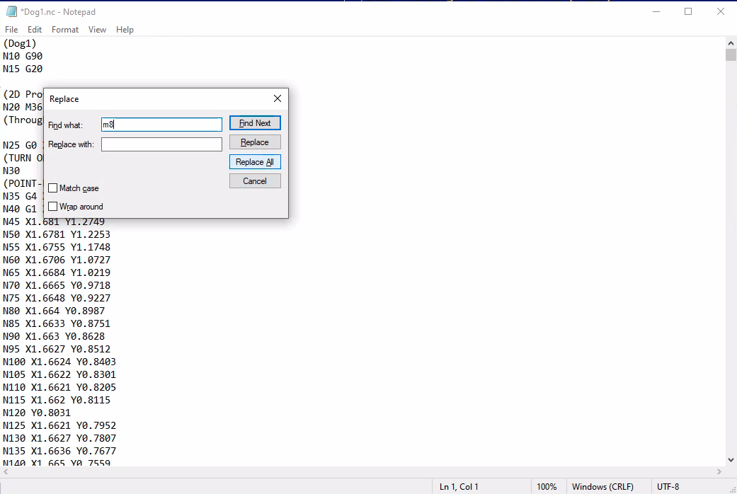
12) Tap edit on the bottom [F6]. Press ctrl+h on the keyboard to open the Replace dialog.
- Find M7, replace with nothing. Click Replace All.
12) Tap edit on the bottom [F6]. Press ctrl+h on the keyboard to open the Replace dialog.
- Find M7, replace with nothing. Click Replace All.
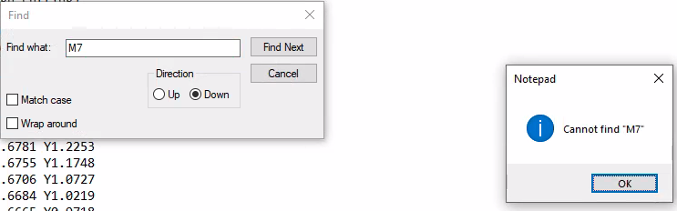
13) Click the Edit menu at the top and select Find [ctrl+f]. Search for the text M7. A dialog should pop up indicating the text cannot be found.
Click File > Save as… [ctrl+shift+s]
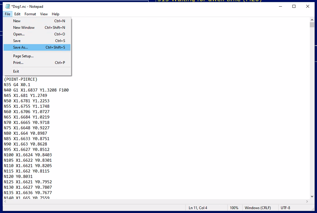
Save the file as a new base file name ending with “Air” prior to the file extension (e.g. Dog1Air.nc).
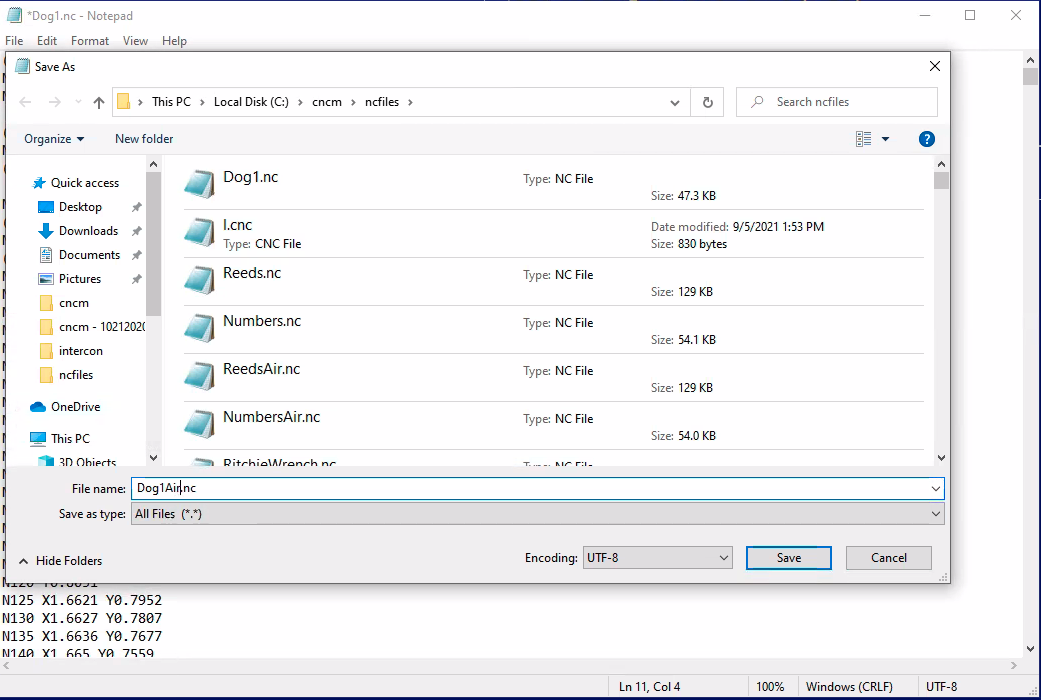
Running this file will simulate the cut using the CNC Plasma Cutter without actually turning on the plasma.
14) Tap Load and load the file saved in the step directly above (e.g. Dog1Air.nc). Validate M7 is not present in the G-code as described above.
15) Tap Graph [F8]. Validate that:
- The material is aligned correctly
- The design shown is as expected
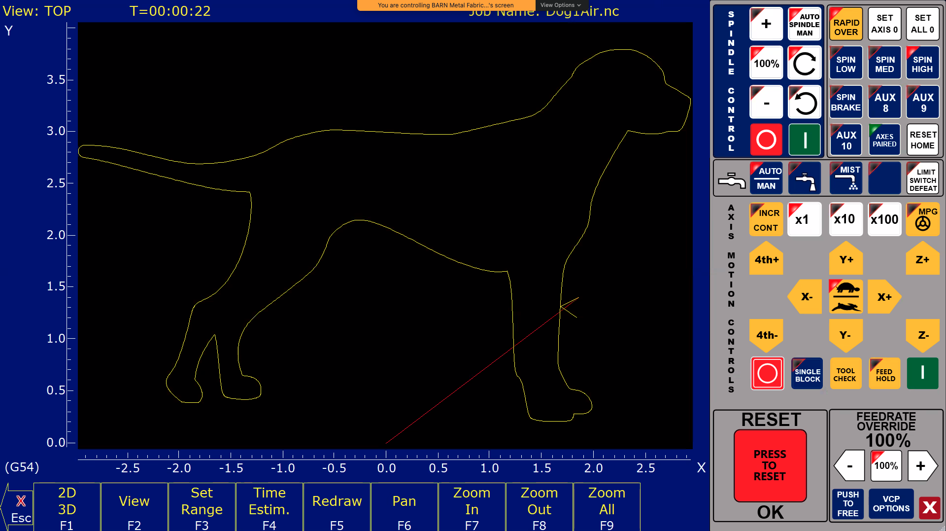
Adjust X0/Y0 and/or material position as necessary.
Once satisfied, press Escape to get back to home screen.
Press Cycle Start. The sample cutter will run without the plasma turned on.
Validate the material will be cut as intended. Re-run using Cycle Start until positioning is sufficient.
Press the Escape key to get back to home screen.
16) Load the original file (e.g. “Dog1.nc”) again to make the actual cut.
17) Turn on the air valve behind the Tubing material near the monitor.
18) Turn on the plasma torch below the table. Adjust settings Settings per manufacture of Plasma.
19) Verify the settings on the plasma cutter per HyperTherm cut sheet (feed rate, voltage, amperage, torch height, etc.)
Press Cycle Start to make the cut.
20) When cut is finished, press Cycle Cancel [escape]. Move the z up and remove material.
21) After session is finished, turn air off, turn plasma cutter off, cover table.
Follow Us