This tutorial will walk you through the steps of converting an SVG to G-Code using Fusion 360. This article is used as part of classes offered in BARN’s Metal Fabrication Studio.
Pro tip: If you are in the middle of an operation and want to cancel, press the Escape key. If you want to undo your last operation, press cmd+z (Mac) or ctrl+z (Windows)
Pro tip: Keyboard shortcuts can make this process a lot quicker and are indicated with square brackets [example hot key]. In cases where Mac/Windows hot keys are different, both are listed, separated by a slash.
Prerequisite: Email metal.lead@bainbridgebarn.org to get an invite to join the BARN Slack group.
1) Open Fusion 360 application.
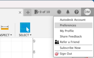
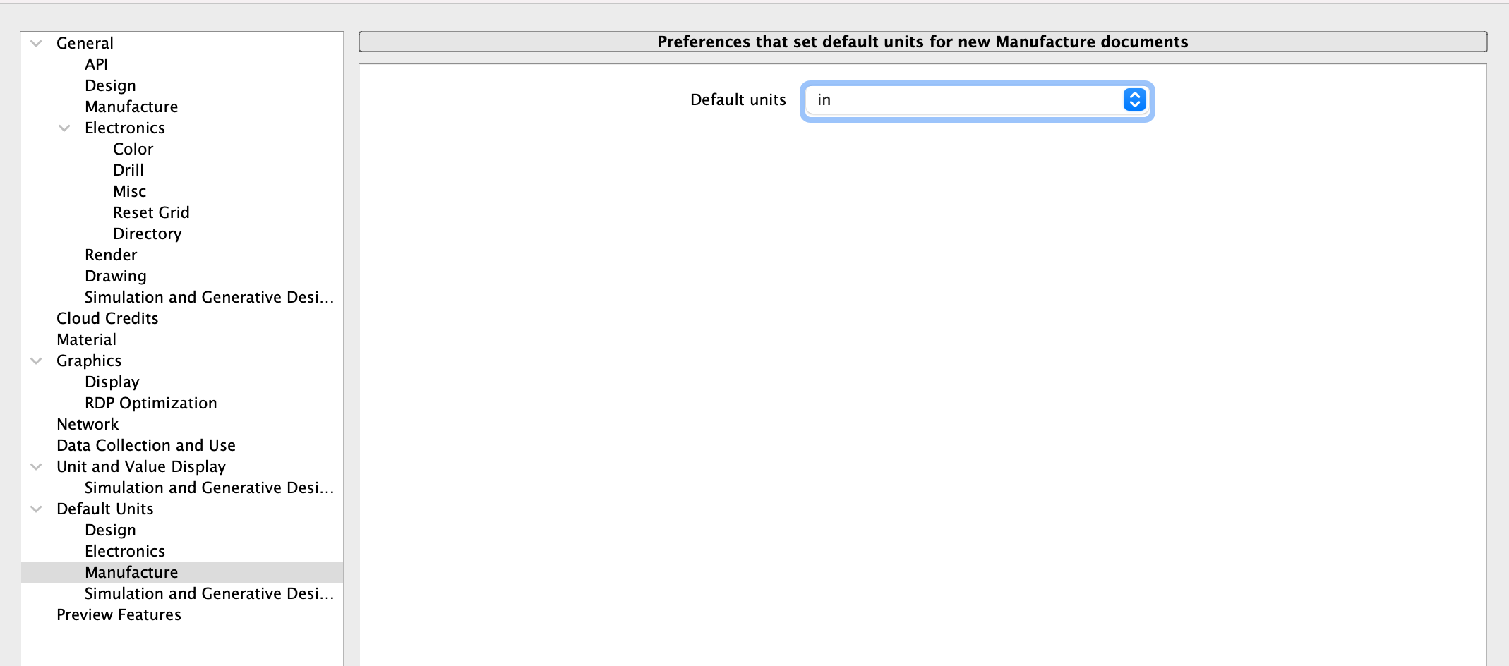
2) Click the circle with your initials in the top right corner. Select Preferences from the dropdown.
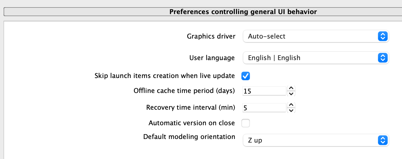
In the Preferences dialog, select “Z up” for the Default modeling orientation.
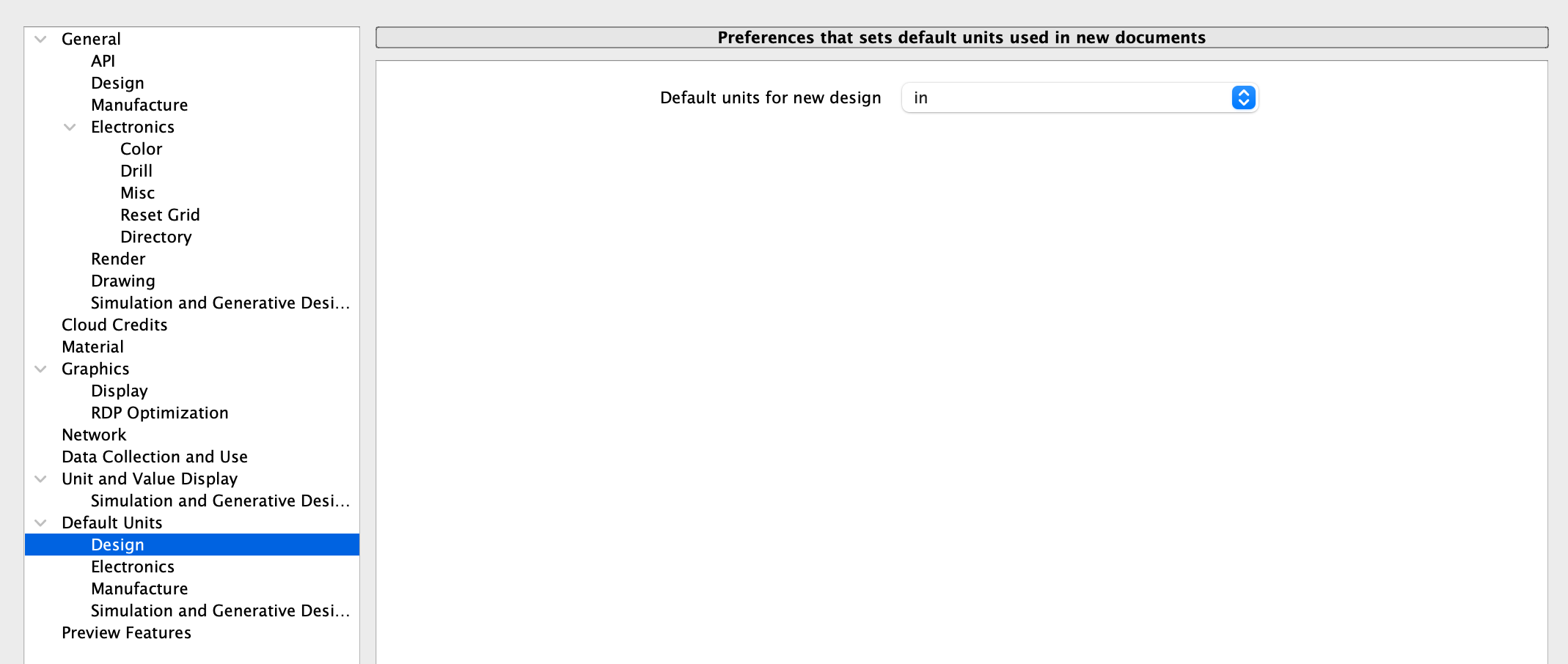
Select “In” for both Design and Manufacture default units. Select OK at the bottom of the dialog.
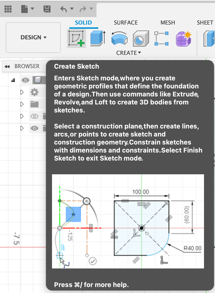
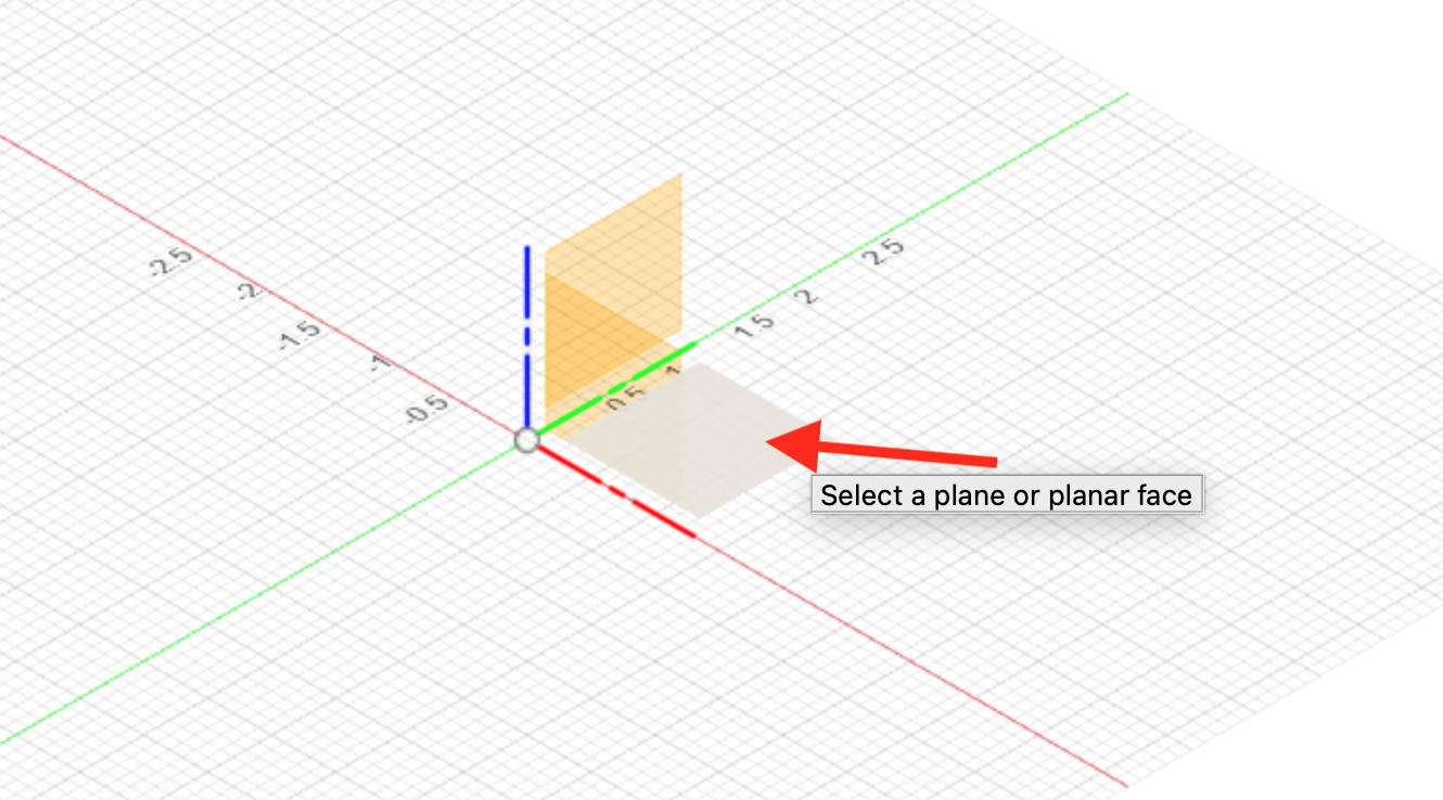
3) Click the Create Sketch tool in the toolbar on the upper left and select the bottom plane.
4) Select the 2-Point Rectangle tool in the toolbar [r] and place the first point on the origin. Drag the rectangle up and to the right and click again to complete the rectangle (the exact dimensions do not matter at this point – they will be set in the next step).
Drag the rectangle up and to the right.
Click again to complete the rectangle (again, the exact dimensions do not matter at this point – they will be set in the next step).

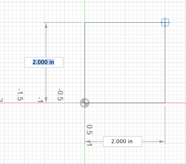
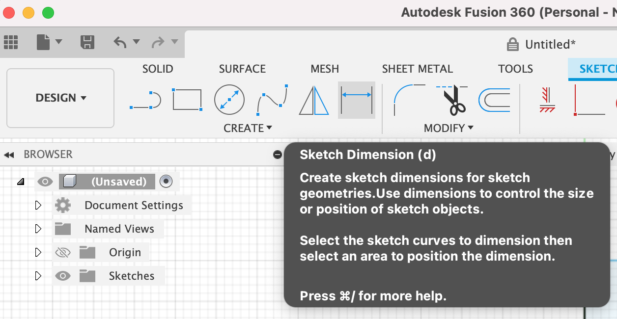
5) Select the Sketch Dimension tool [d] in the toolbar.
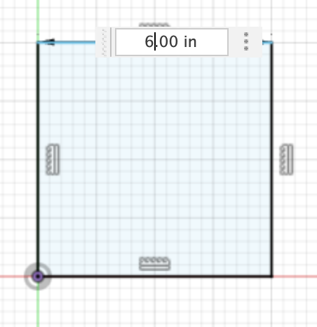
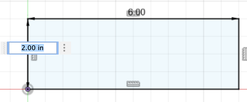
Double-click on the top side of the rectangle and enter the desired width of your image – this is the width that will ultimately be cut on the CNC Plasma Cutter. Press the enter/return key to set the width. Double-click on the left side of the rectangle, enter the desired height, and press the Enter/Return key.
The rectangle should now reflect the desired size.
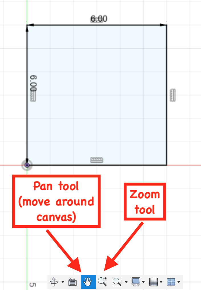
Pro tip: If you want to navigate around the canvas and/or zoom in/out, use the bottom toolbar.
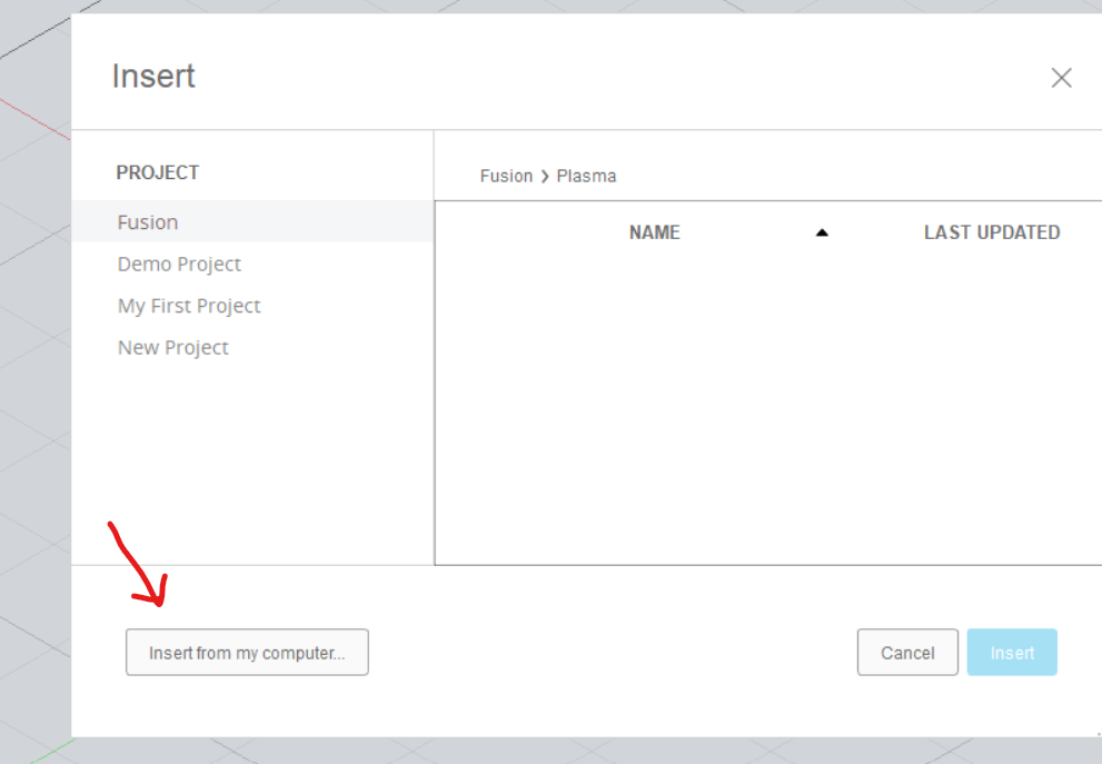
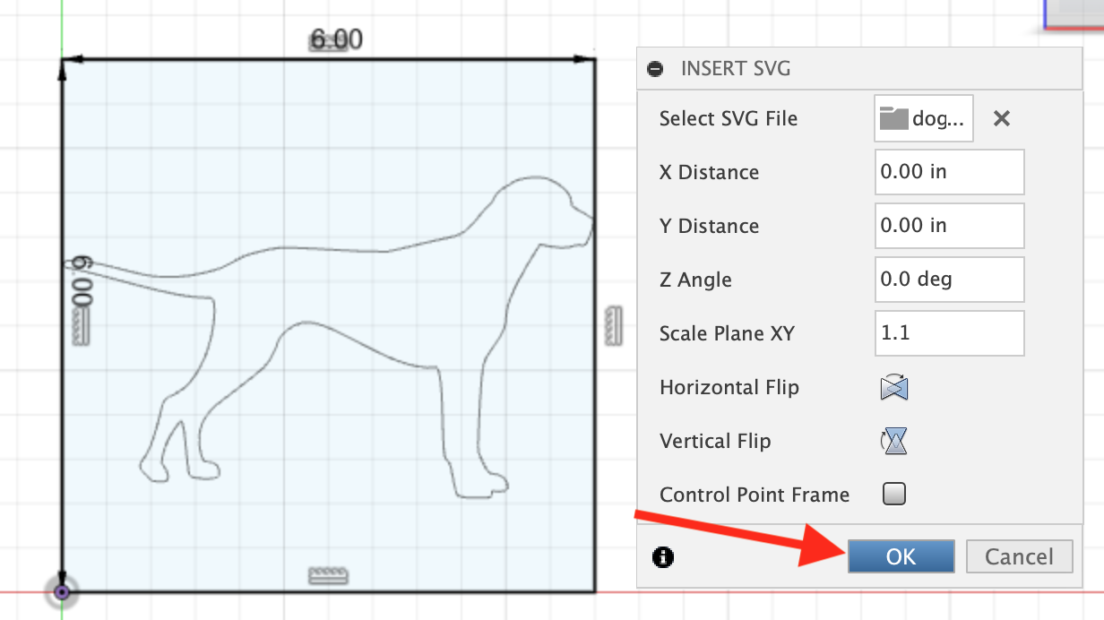
6) Click on the small down arrow next to the word Insert on the right side of the toolbar. From the drop-down menu, click Insert SVG.

7) Select “Insert from my computer…” and select the SVG that you want to cut with the CNC Plasma Cutter (in most use cases, you will have just created this with Inkscape).
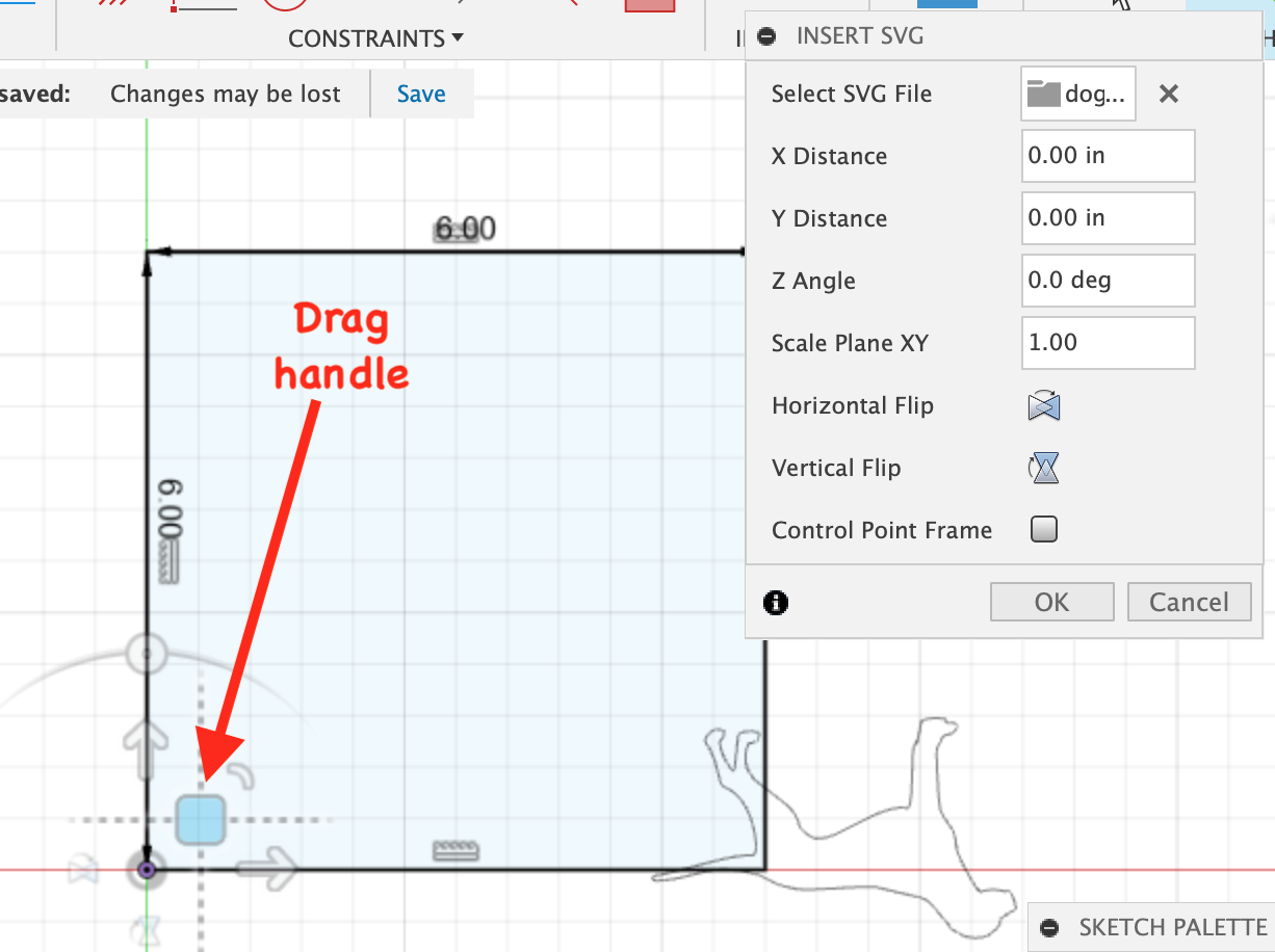
8) Manipulate the SVG image as described below. Note that any time a drag operation is completed, the text values in the Insert SVG dialog will be effectively set to 0 (even though they may not change). Any subsequent changes will be relative to the current image, not the original image.
- Positioning
- Drag & drop: Click on the square drag handle that rendered on the plane when the image was inserted. Hold down the mouse and drag to position the SVG image inside the rectangle.
- Precise positioning can be set by changing the X Distance and Y Distance in the Insert SVG dialog. Note that after completing a drag operation, the text values will represent relative changes to the current position (not the initial position).
- Flip
- Use the Horizontal flip/Vertical flip buttons in the Insert SVG dialog as necessary to manipulate the image as desired.
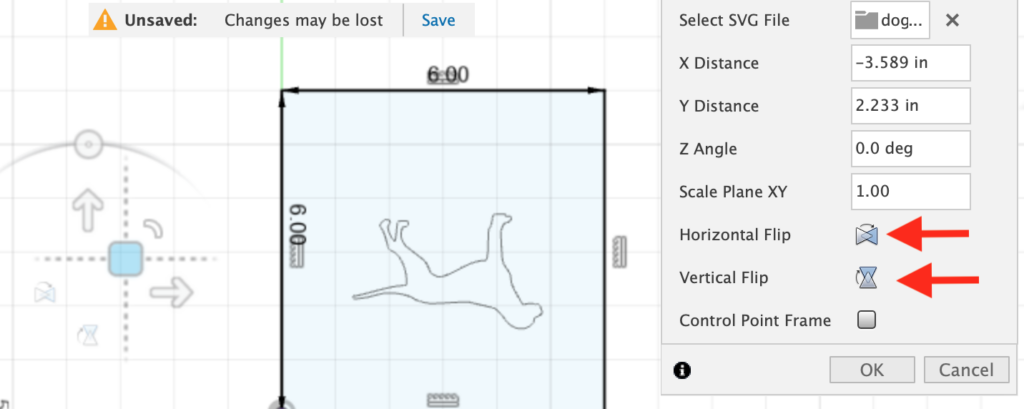
- Scale
- Adjust the XY Scale Plane as necessary to fit the SVG completely inside the rectangle.
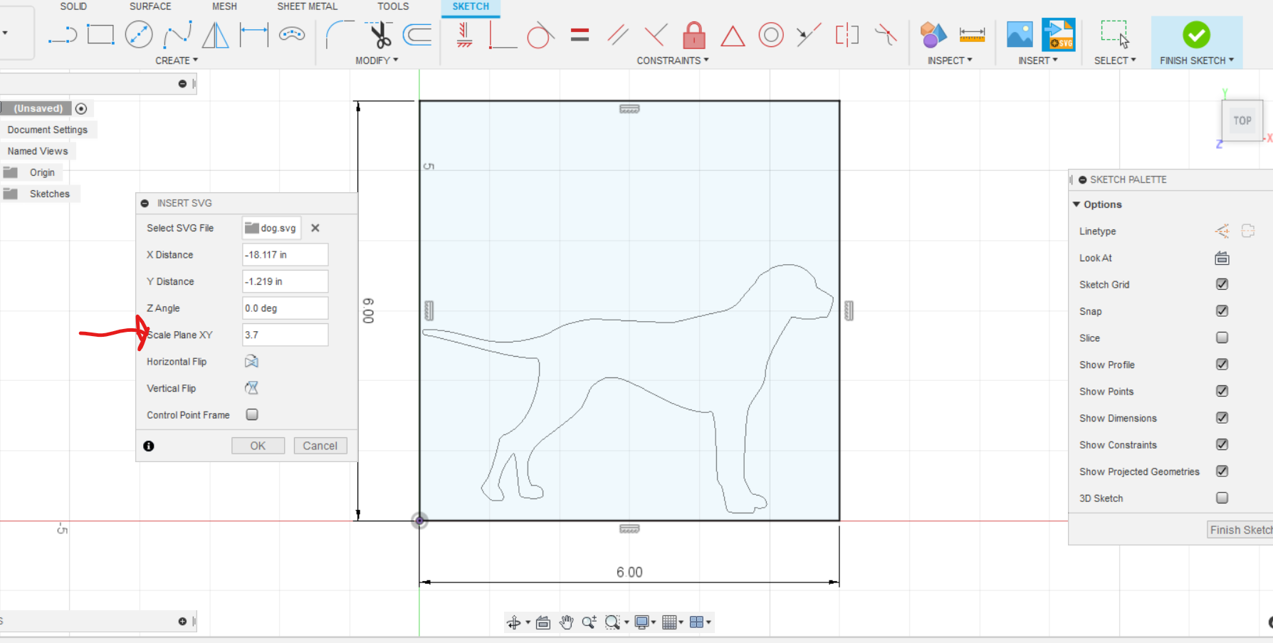
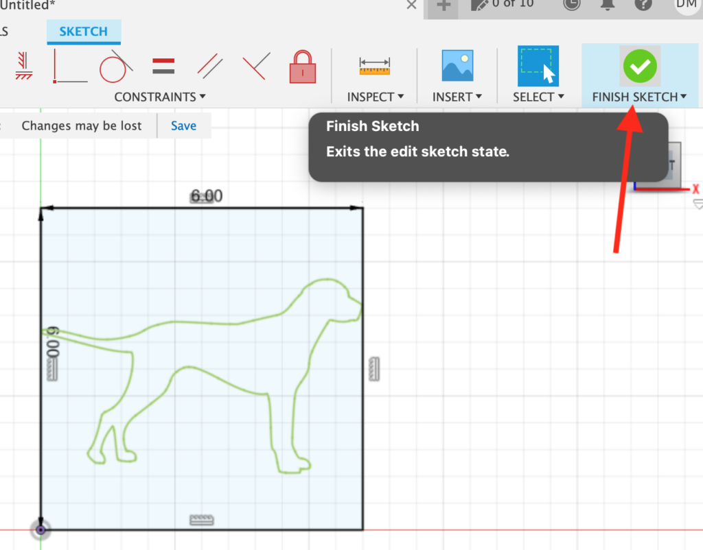
9) Click OK on the Insert SVG dialog
Click Finish Sketch in the upper right.
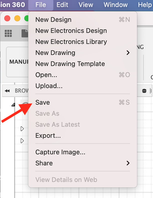
10) Click on the File menu at the top and select Save [cmd+s/ctrl+s]. Name the file and save it to folder of your choosing.
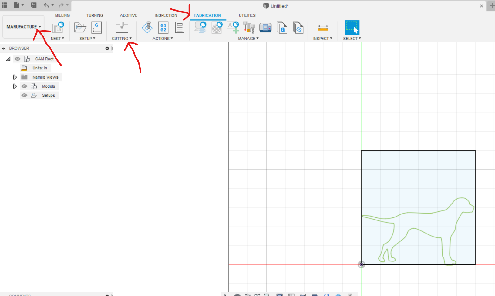
11) Change from Design mode to Manufacture mode using the top-left dropdown. Select the Fabrication tab.
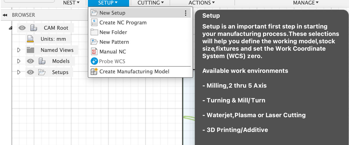
12) Select the Setup tool in the toolbar and New setup from the dropdown. Make the following changes in the Setup dialog using the tabbed interface at the top of the dialog:
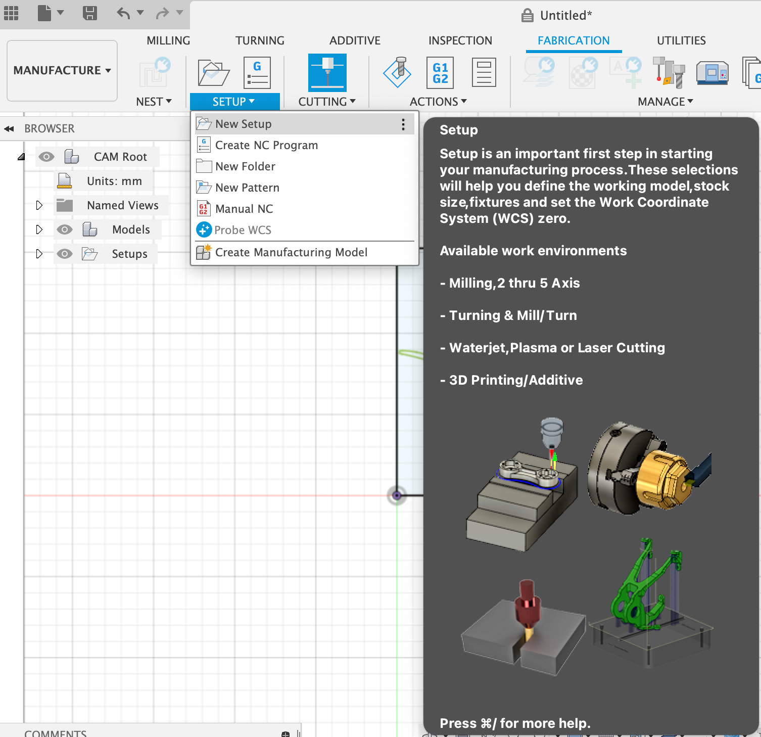
- On the first tab (Setup – indicated with white/blue box icons):
- Change Origin to Selected point using the dropdown.
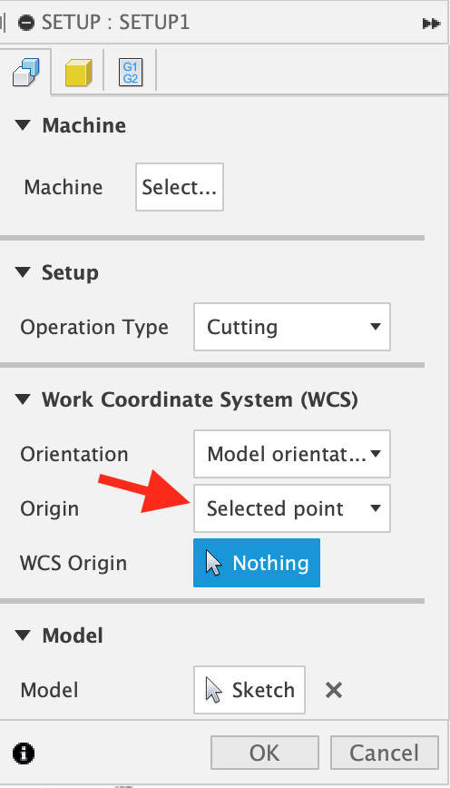
- On the second tab (Stock – indicated with yellow box icon):
- Change Mode to Fixed size box with the dropdown
- Change Height (Z) to 0.125 in with the text input
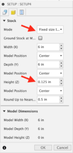
- On the third tab (Post-process – indicated with black/blue document icon):
- Change the Program Name/Number to a name of your choice so it can be used in the future
Click OK at the bottom of the dialog to accept these changes.
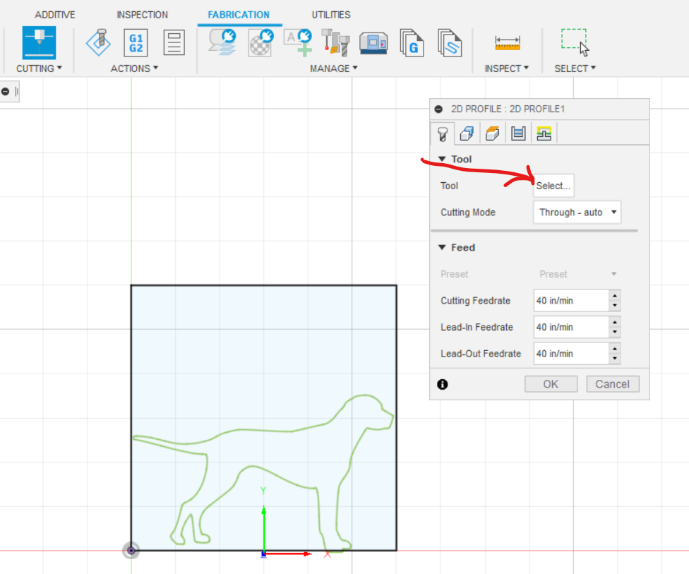
13) Select the 2D cutting tool using the top toolbar. On the 2D Profile dialog, select the Tool tab and then click the button that shows “Select…”
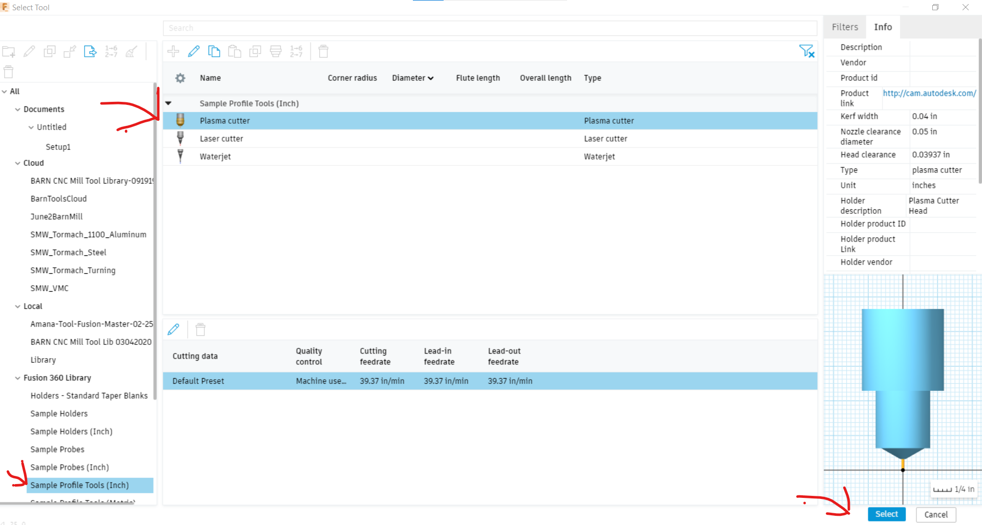
The Tool Library dialog will open. Select Sample Profile Tools (Inch) and then Plasma Cutter
Click the blue Select button in the lower right.
14) The main canvas should be open again. Click on the Geometry tab on the 2D Profile dialog.
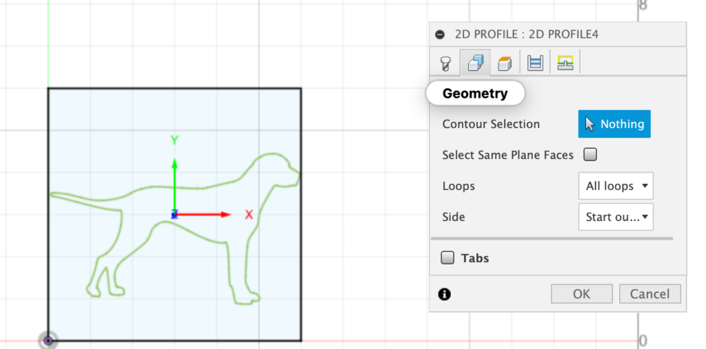
Click the line on the SVG and a blue outline will render on the SVG. Press OK in the 2D Profile dialog to accept.
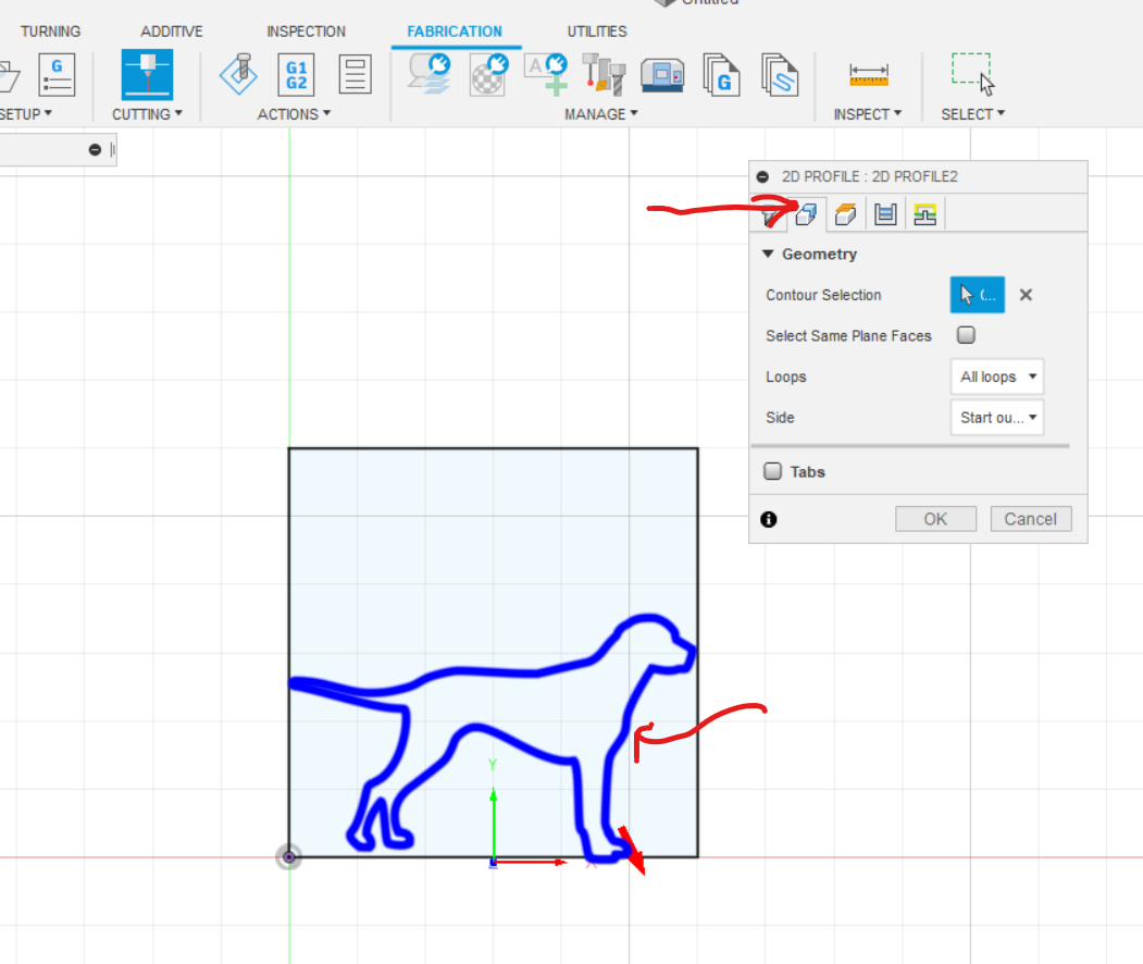
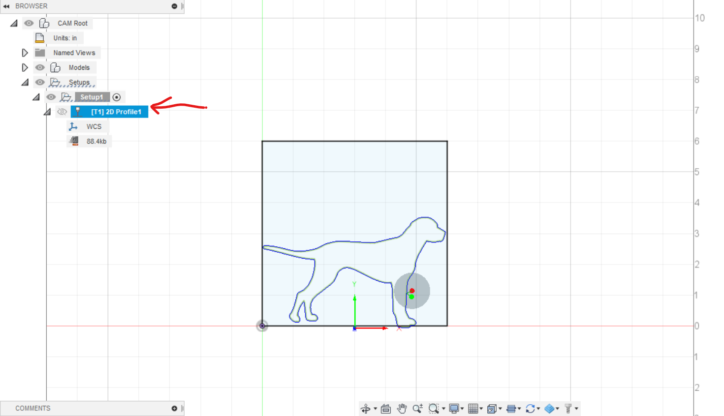
The tool path will be generated if there are no issues. If there are issues, a warning triangle icon will show in the design tree. Read the error and troubleshoot as necessary.
15) In the Actions section of the top toolbar, click on Simulate. Click on the play button (right-pointing triangle) arrow at the bottom of the screen to start the simulation. Simulate mode can be exited by clicking Close at the bottom of the Simulate dialog.
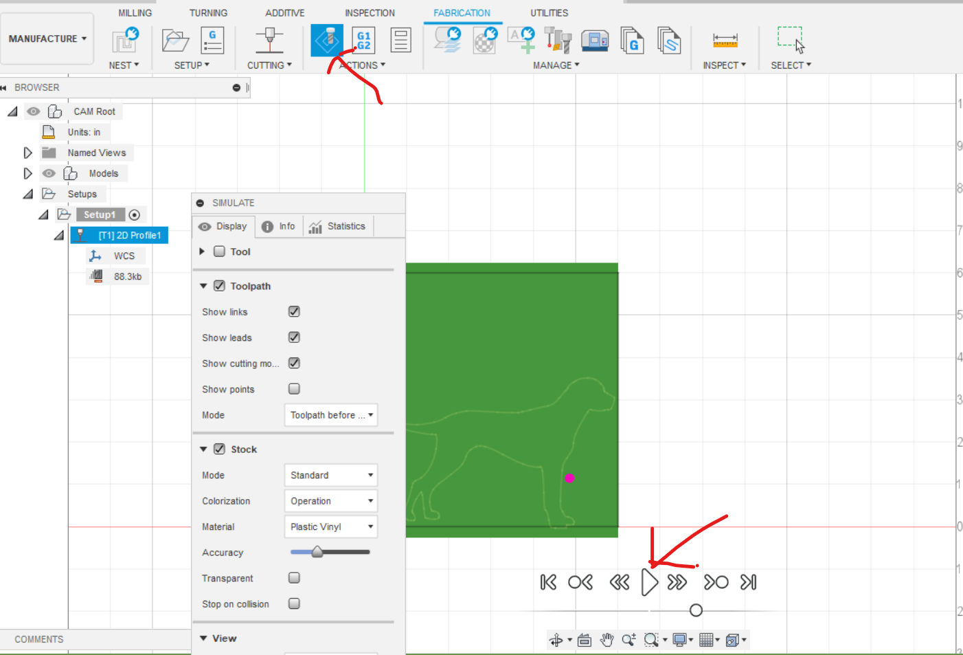
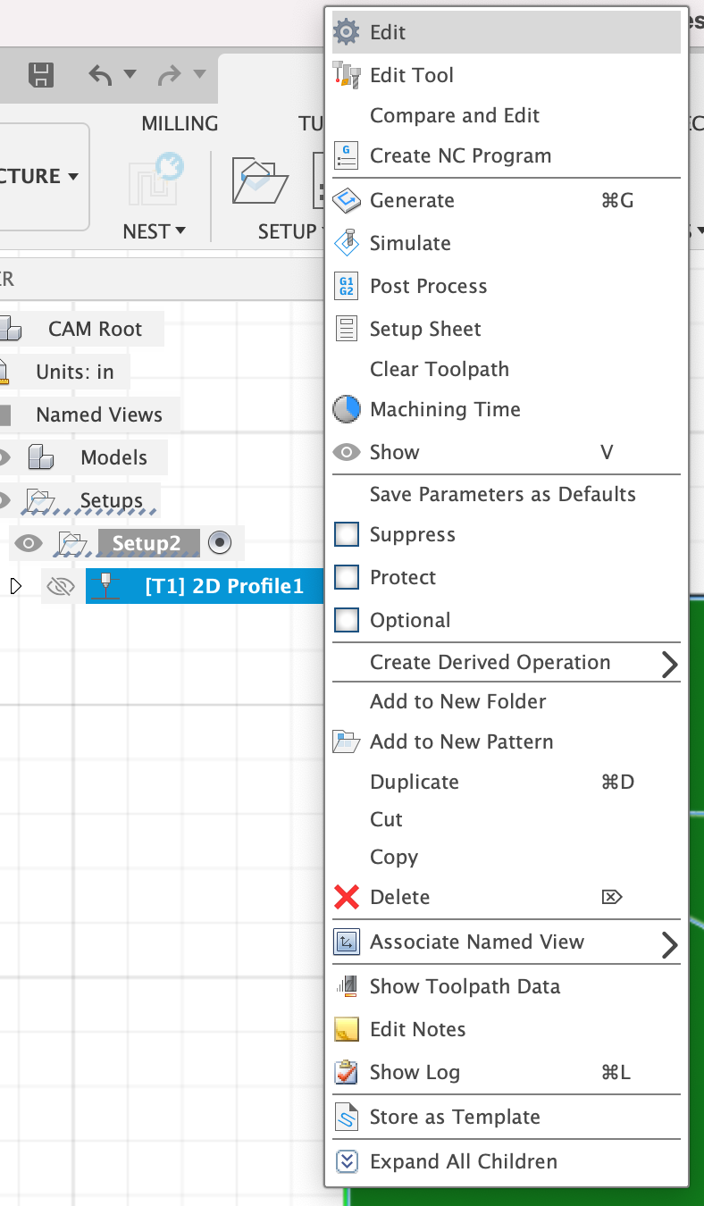
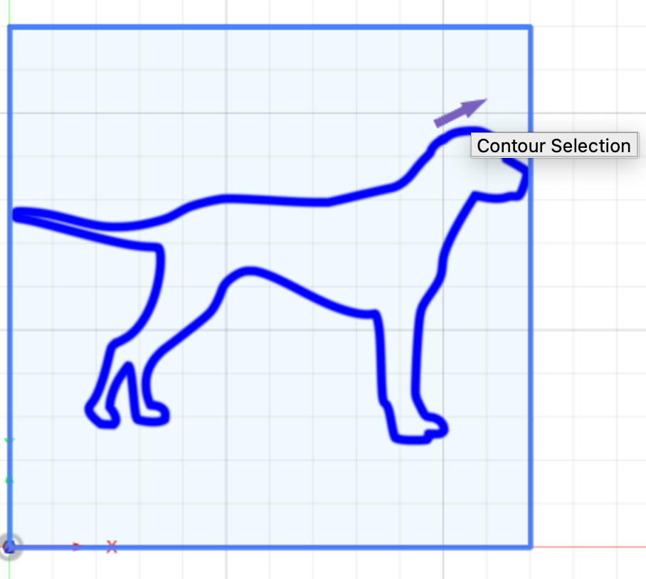
This shows the cut the CNC Plasma cutter will make. If you need to make any changes to this path, right-click the Profile (it will have a name like “[T1] 2D Profile 1”) and select Edit at the top of the dropdown.
You will notice in the simulation there are small diagonal lines outside of the SVG – those are the lead-in and lead-out lines for the CNC plasma cutter. They should lead in/out from the waste material, not the finished piece.
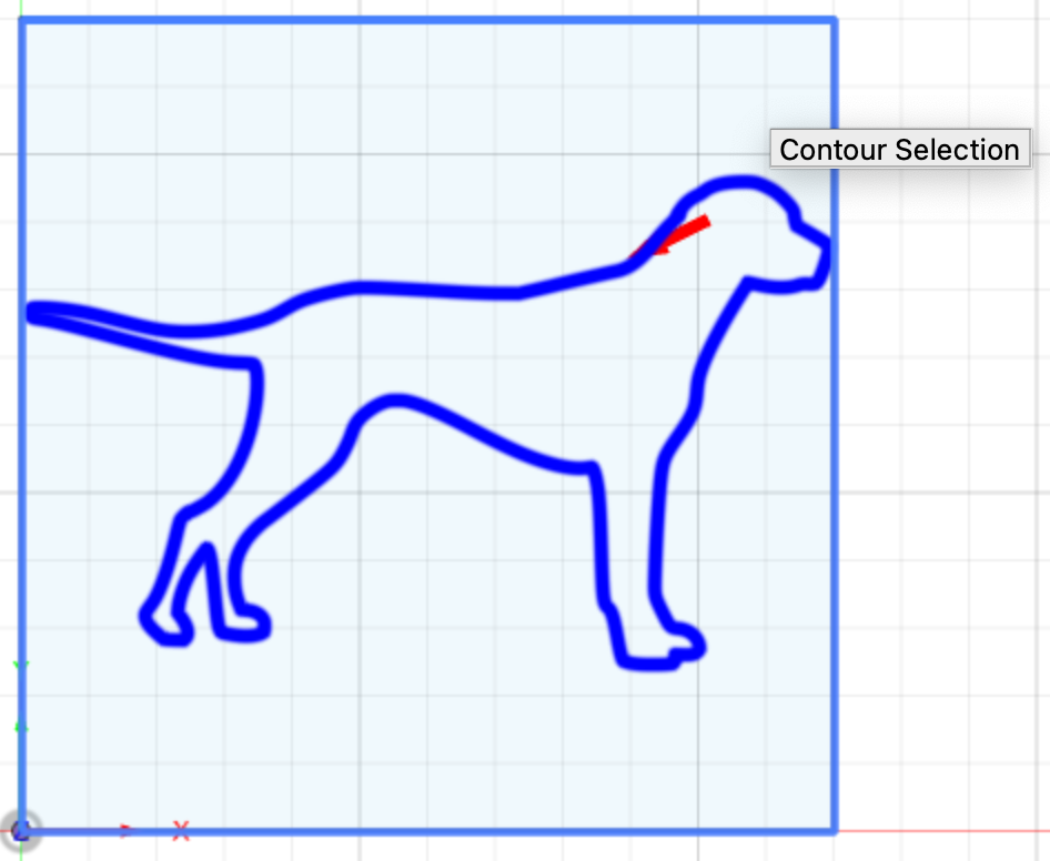
If you need to flip those lines to the other side of the cut, select the Geometry tab at the top of the 2D Profile dialog and click the red arrow that renders alongside the SVG. The red arrow should move to the other side of the line.
Make any other needed changes to the cut, click OK in the 2D Profile dialog, and run the simulation again per directions above until the cut meets your specifications.
16) Download the latest CNC Plasma Cutter on a pinned message on the #mtl-cnc-plasma-table Slack channel.
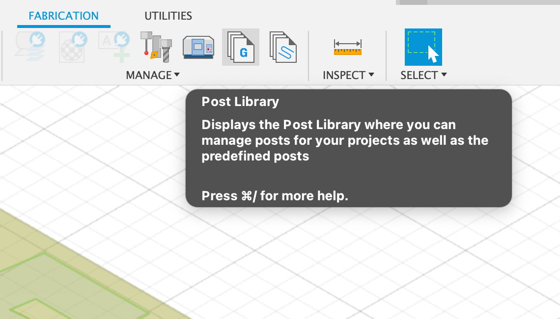
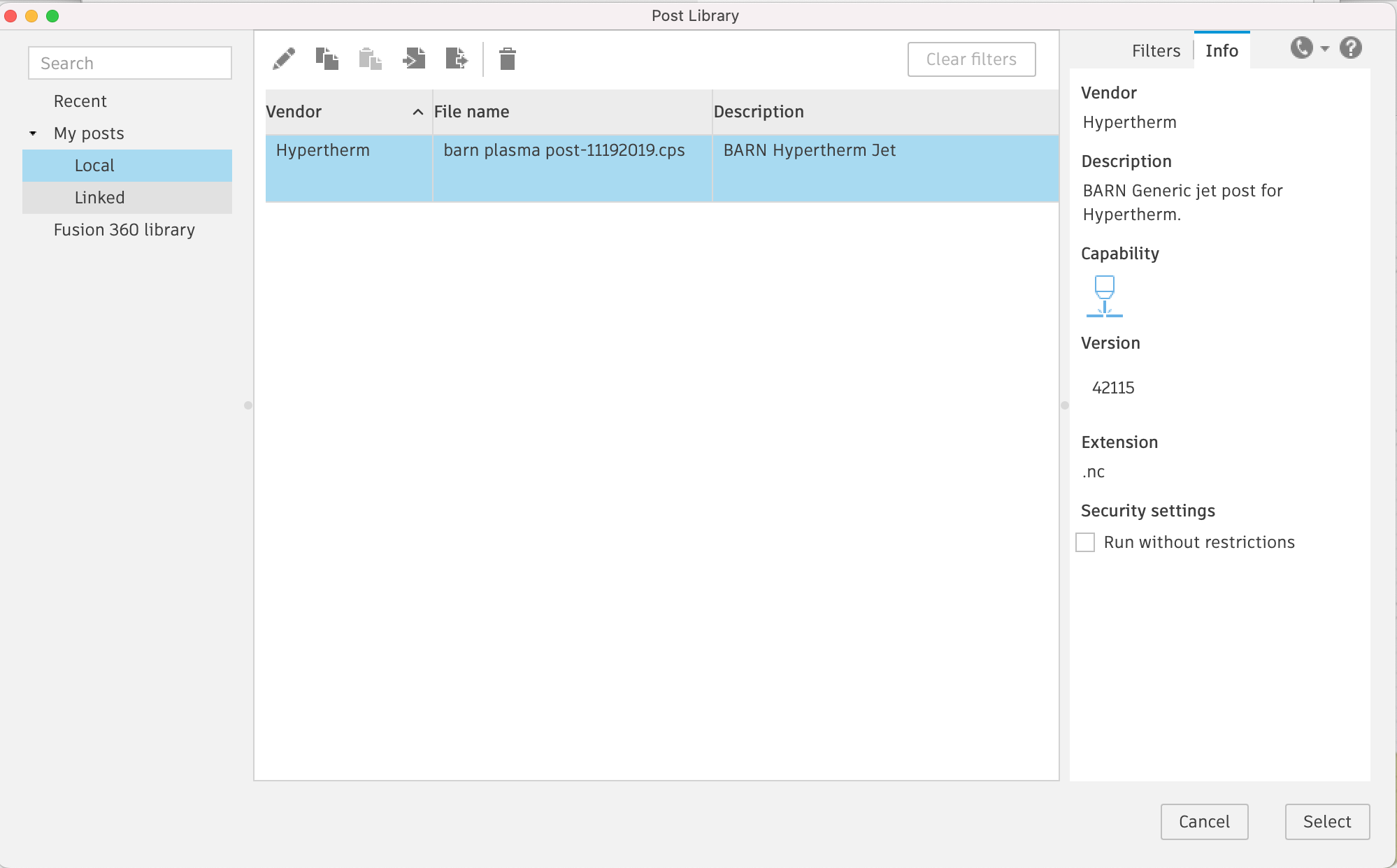
17) In the Manage section in the top toolbar, select Post Library as indicated by the G pages icon.
The Post Library dialog will open. Select Local from the left pane. Click the Import button at the top of the dialog. Select the post-processor file you downloaded in the previous step.
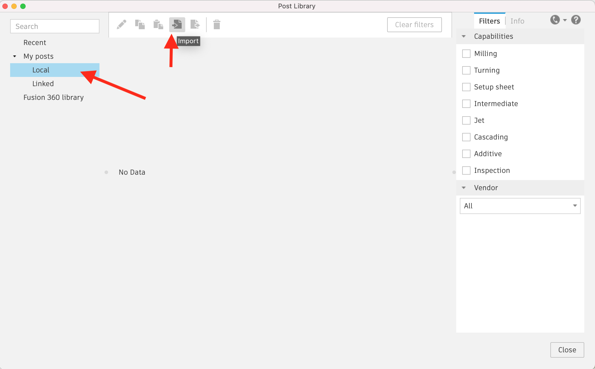
The new post-processor should show up. Close the Post Library dialog.
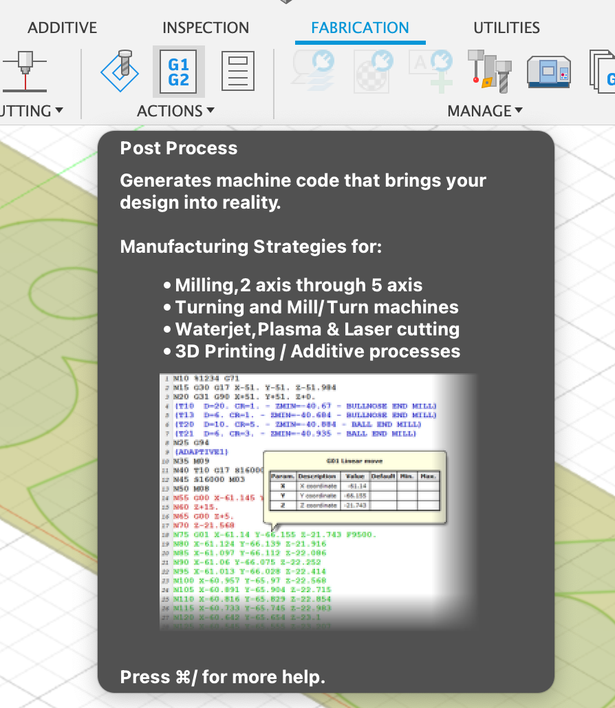
18) In the Actions section in the top toolbar, click the Post Process button as indicated by the G1 G2 icon.
In the Post field, select Choose from library
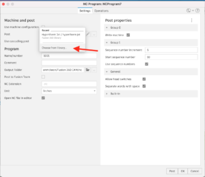
In the Post field, select Choose from library
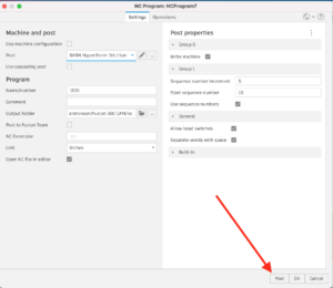
Click the Post button at the bottom and save to a thumb drive.
Follow Us